


Electron Microscopy, Metrology, Inspection & Defect Review
The control of the vacuum environment used in the field of electron microscopy, metrology, inspection & defect review requires high-precision vacuum v...
Read more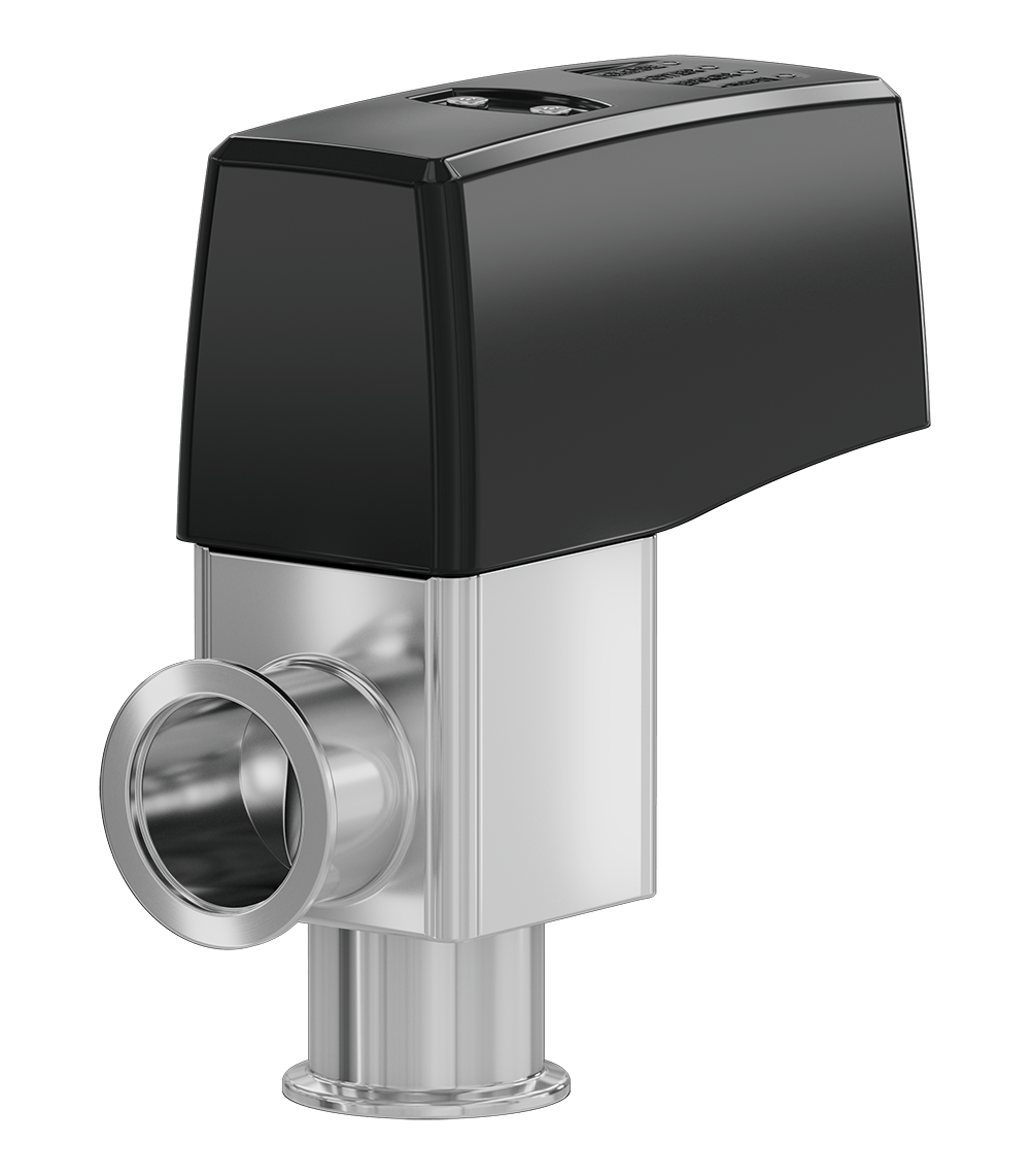
The key performance indicators for angle valves are reliability and variability. The 26.4 HV Angle Valve series delivers both. Tested in thousands of demanding applications under various process conditions the 26.4 series has proven its outstanding reliability and variability.
With its design options in actuation from manual to pneumatic to electric, various flange connections, body materials and sealing materials, nearly every requirement can be met.
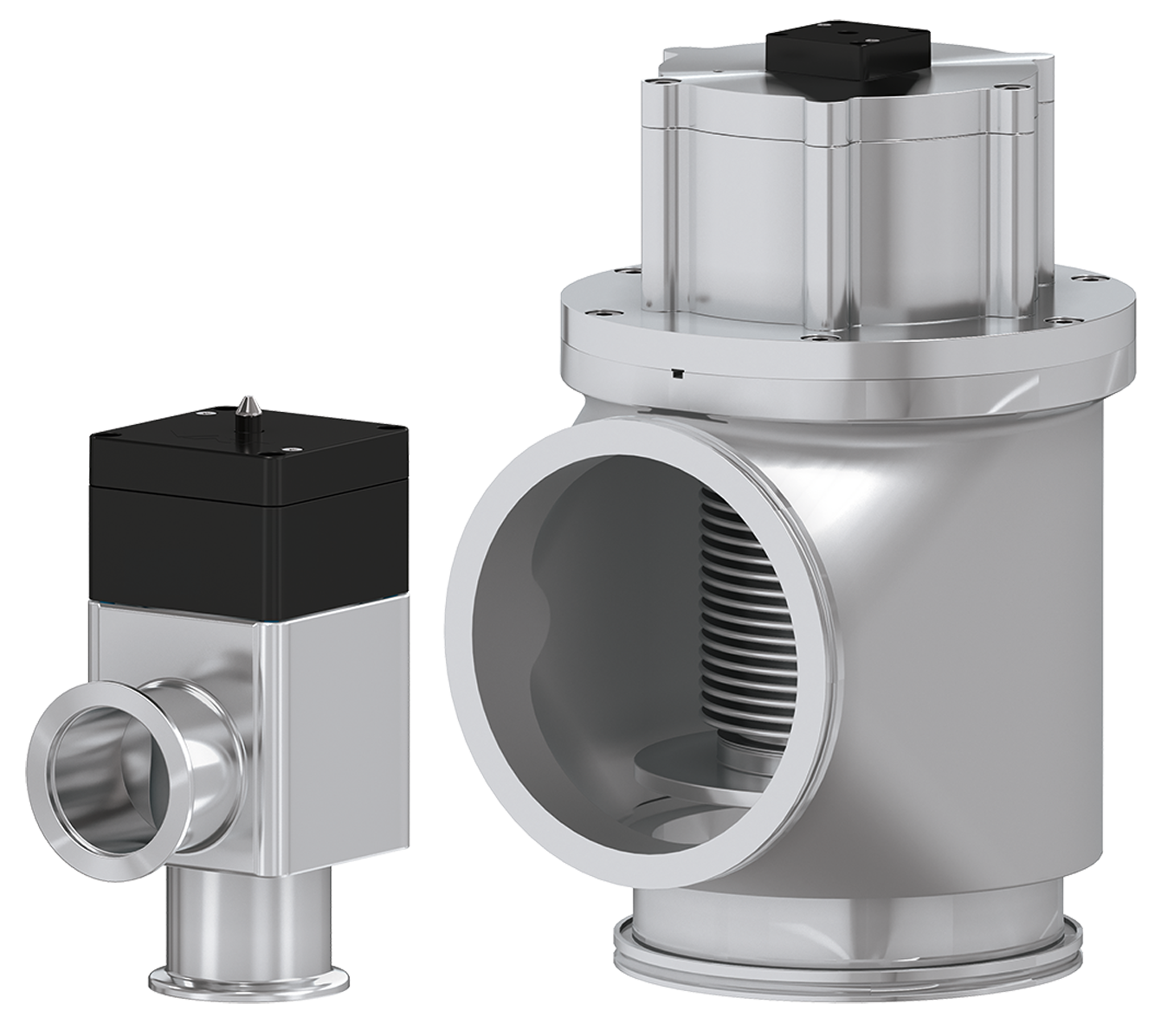
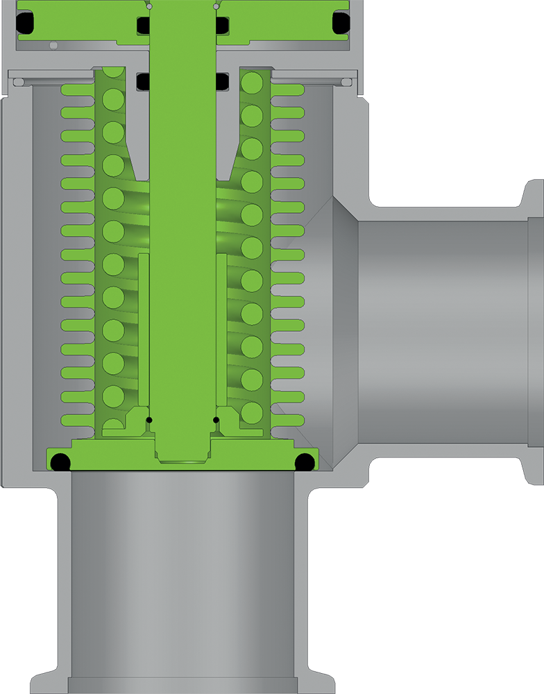
The 26.4 is ideal for the pumping and venting of HV systems when a low outgassing rate is important. It resists high differential pressure and is fitted with a bellows-encapsulated feedthrough for particle-sensitive applications. The bellows encapsulation also prevents pressure peaks in any valve position.
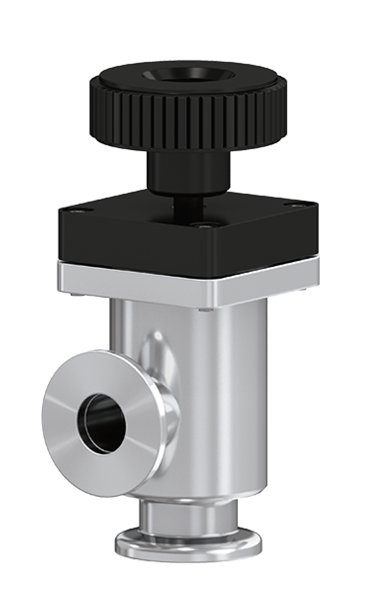
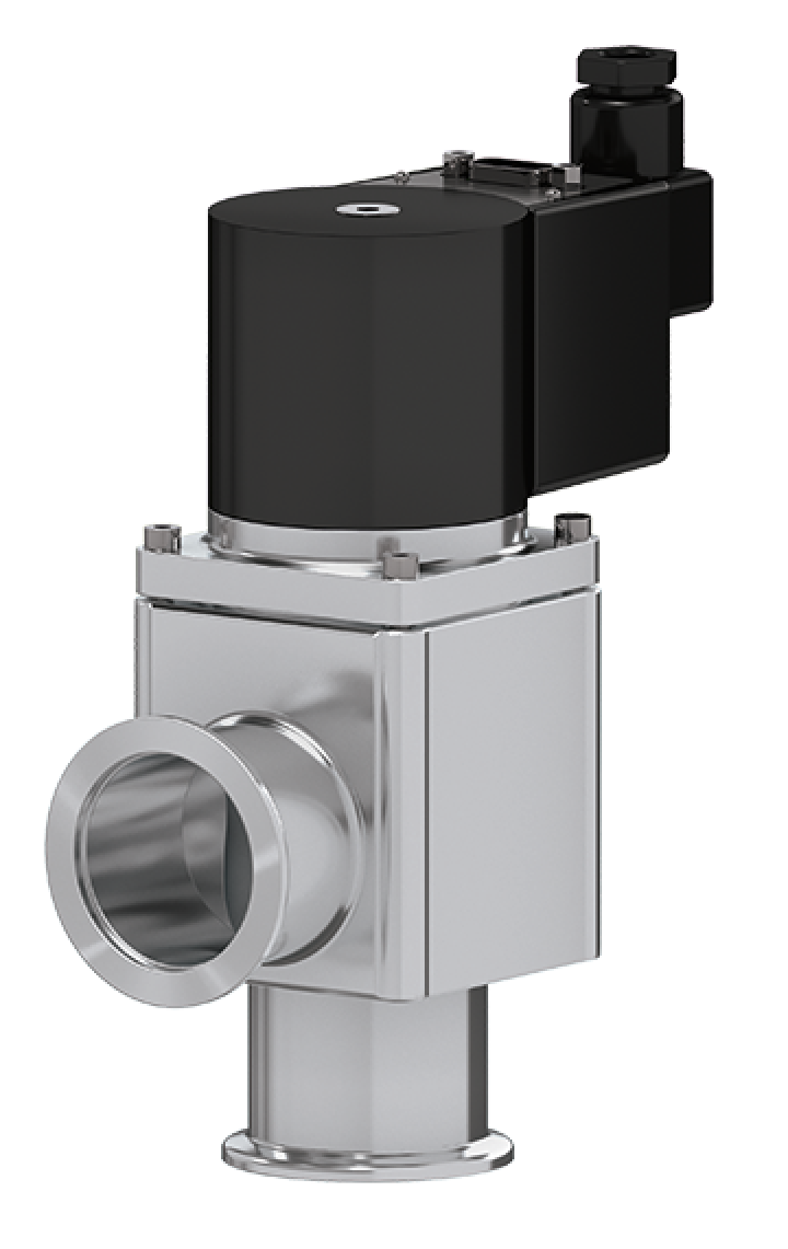
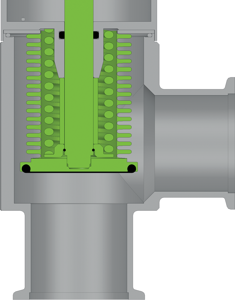
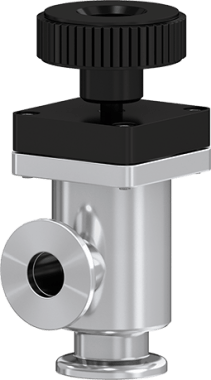
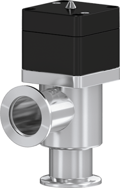
Based on a reliable and robust core design, the 26.4 HV Angle Valve offers different actuation options. The manual version is controlled by a removable hand wheel that provides good grip and precise control with a clear end stop position, avoiding the risk of over twisting. The pneumatic version can be configured as single acting with closing spring (NC), opening spring (NO) or double acting.
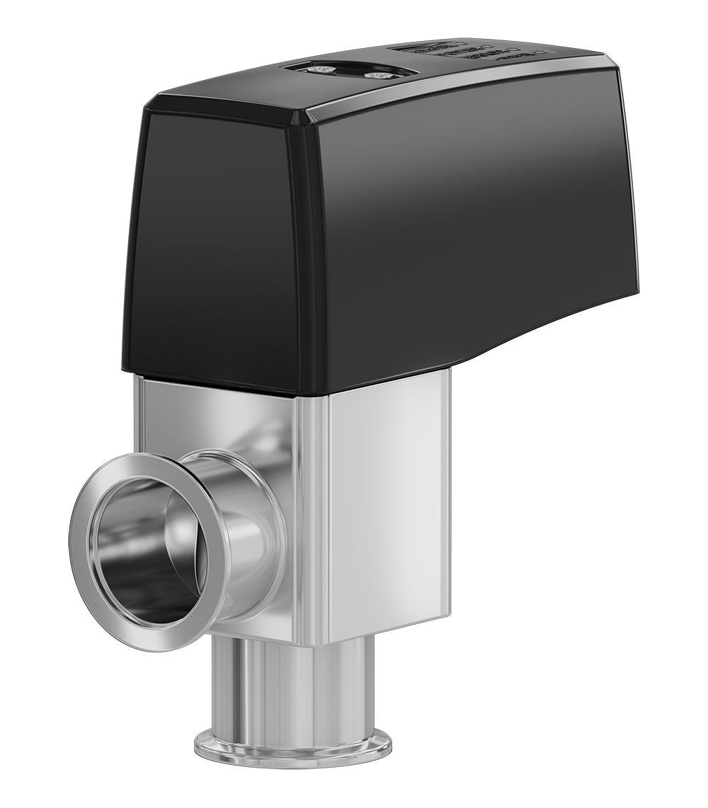
The pneumatic version is controlled by a solenoid valve either “on board” or in a distant location if required. The electric version is actuated by a stepper motor supplied as normally closed using a 24V DC power supply. It is designed to meet specific requirements in low power consumption, high cycle time, reduced vibration and low noise. In this regard it is an alternative for applications were pneumatic actuated valves do not satisfy these objectives.
The manual and pneumatic version are available in sizes from DN 10 to DN 160 mm (0.4" – 6.4") and the electrical version is available in sizes from DN 16 to DN 40 mm (5/8" – 1.5").
The 26.4 can be selected in aluminum or stainless steel in various specifications. The standard options for flange connectors are ISO-KF or ISO-K (for the electric version only ISO-KF). The 26.4 can be used in different temperature regimes depending on the sealing elastomer chosen. In addition to these standard options further customization is possible.
The 26.4 HV Angle Valve series is also available as 26.5 as an inline version.
Features:
Benefits:
| Sizes | DN 10 (⅜"), DN 16 (⅝"), DN 25 (1"), DN 40 (1½"), DN 50 (2"), DN 63 (2 ½"), DN 80 (3"), DN 100 (4"), DN 160 (6") | ||
|---|---|---|---|
| Actuators | Manual | with removable handwheel | |
| Pneumatic | single acting with closing spring (NC) or opening spring (NO), or double acting | ||
| Electromagnetic | single acting with closing spring (NC) | ||
| Electric | stepper motor (NC) | ||
| Body Material | aluminum or stainless steel | ||
| Feedthrough | bellows | ||
| Standard Flanges | ISO-KF, ISO-K, ISO-KF 40 | ||
| Leak Rate | Valve body, valve seat | < 1 × 10⁻⁹ mbar ls-1 | |
| Pressure Range | Manual/pneumatic actuator
Electric actuator | 1 × 10⁻⁸ mbar to 5 bar (DN 10– 50) 1 × 10⁻⁸ mbar to 2 bar (DN 10– 40) 1 × 10⁻⁸ mbar to 5 bar (DN 10 – 40) | |
| Differential Pressure on the Plate | Manual/pneumatic actuator | ||
| in opening direction | ≤ 2.0 bar (DN 10 – 50) | ||
| ≤ 1.2 bar (DN 63 – 160) | |||
| in closing direction | ≤ 5.0 bar (DN 10 – 50) | ||
| ≤ 4.0 bar (DN 63 – 80) | |||
| ≤ 2.0 bar (DN 100 – 160) | |||
| Electromagnetic actuator | ≤ 2.0 bar (DN 10 – 40) | ||
| Electric actuator | ≤ 2.0 bar (DN 10 – 40) | ||
| Cycles until first Service | Manual actuator | 10 000 (DN 10 – 160) | |
| Pneumatic actuator | 3 million (NC, NO) (DN 10 – 80) | ||
| 1 million (NC, double acting) (DN 100 – 160) | |||
Electromagnetic | 200 000 (DN 10 – 40) | ||
| Electric actuator | 2 million (DN 10 – 40) | ||
| Temperature | Valve body | Manual/pneumatic actuator Electromagnetic actuator Electric actuator | ≤ 150 °C ≤ 150 °C |
| Actuator | Manual/pneumatic Electromagnetic Electric | ≤ 120 °C ≤ 50 °C ≤ 50 °C | |
| Solenoid valve & position indicator | ≤ 80 °C (DN 10 – 80) ≤ 50 °C (DN 100 – 160) | ||
| Material | Aluminium valve body | EN AW-6060 (3.3206), EN AW-6061 (3.3211), (DN 16 – 63) EN AW-6063 (3.3206), EN AW-6082 (3.2315) EN AC-42000 (DN 80 – 160) | |
| Stainless steel valve body | AISI 304 (1.4301) (DN 10 – 50) AISI 316L (1.4404) (DN 63 – 160) | ||
| Plate | AISI 316L (1.4404, 1.4435) | ||
| Bellows | AISI 316L (1.4404, 1.4435), AISI 316 Ti (1.4571) | ||
| Seal | Bonnet, plate | FKM | |
| Mounting Position | any | ||
| Solenoid Valve | 24 VDC, 2.5 W (others on request) (DN 10 – 80) 24 VDC, 1.0 W (others on request) (DN 100 – 160) | ||
| Position Indicator: Contact Rating | Voltage | Manual/pneumatic actuator Electromagnetic actuator | 5 – 50 VAC / DC max. 48 VAC / DC |
| Current | Manual/pneumatic actuator Electromagnetic actuator | 5 – 100 mA max. 500 mA | |
| Mains Voltage | Electromagnetic actuator | 100 – 120 V / 200 – 240 V / 50 – 60 Hz | |
| Operating Frequency | Electromagnetic actuator | max. 15 min-1 at 20 °C | |
| Valve Position Indication | visual (mechanical) | ||